Most software developers have stared at a messy requirements doc and wondered: "What exactly is supposed to happen here, and in what order?" That gap between a written spec and working code is where bugs, scope creep, and missed edge cases live. A BPMN process diagram closes that gap by turning ambiguous workflows into visual, logic-driven maps that both developers and non-technical stakeholders can understand. If you're building anything with business logic APIs, microservices, user flows, or backend automations knowing how to read and create BPMN diagrams saves you hours of miscommunication and rework.
What Does a BPMN Process Diagram Actually Look Like?
A BPMN (Business Process Model and Notation) process diagram uses a standardized set of shapes and connectors to represent a workflow. Events are circles, activities are rounded rectangles, gateways are diamond shapes, and sequence flows are arrows connecting them. The standard BPMN notation symbols are intentionally designed so anyone developer, product manager, or QA tester can read the same diagram without a legend.
For a software developer, think of it as a visual pseudocode. Instead of writing nested if/else blocks in comments, you draw them. The notation handles parallel paths, error handling, timers, messages between systems, and loops all things developers deal with daily.
Why Should Software Developers Care About BPMN?
You might think BPMN is a "business analyst thing." It's not. Here's why developers benefit directly:
- Requirements become unambiguous. A diagram with gateways and conditions replaces five paragraphs of vague prose.
- Edge cases surface visually. When you map a process, missing branches become obvious something a plain text spec hides.
- Code structure maps to the diagram. Many developers use BPMN diagrams as the skeleton for state machines, workflow engines (like Camunda, Temporal, or AWS Step Functions), or even API endpoint design.
- Cross-team alignment. When QA, product, and engineering all reference the same diagram, "I thought it worked differently" conversations drop significantly.
A Real BPMN Process Diagram Example for Developers
Let's walk through a concrete example: an e-commerce order processing flow.
Imagine you're building the backend for an online store. A customer places an order, and the system needs to:
- Receive the order request
- Validate payment
- Check inventory
- If both succeed, confirm the order and trigger shipping
- If payment fails, notify the customer
- If inventory is unavailable, suggest alternatives or cancel
Here's how that maps to BPMN elements:
- Start Event (circle): Customer submits order
- Task "Validate Payment" (rounded rectangle): Calls the payment gateway API
- Exclusive Gateway (diamond with "X"): Payment valid? → Yes path / No path
- Task "Check Inventory" (rounded rectangle): Queries the inventory service
- Exclusive Gateway: In stock? → Yes path / No path
- Parallel Gateway (diamond with "+"): If confirmed, simultaneously trigger "Send Confirmation Email" and "Initiate Shipping"
- End Events (bold circle): Order confirmed, order cancelled, or payment failed notification sent
This single diagram tells every developer on the team exactly what the system does, what decisions it makes, and where things can go wrong before anyone writes a line of code.
How BPMN Maps to Actual Code Structures
Developers often ask: "How do I go from a diagram to code?" The mapping is more direct than you'd expect:
- Tasks → API calls, function calls, or service invocations
- Exclusive gateways → if/else or switch/case logic
- Parallel gateways → Promise.all(), fork/join patterns, or concurrent threads
- Events (especially timer and message) → Webhooks, cron jobs, or event-driven listeners
- Error events → Try/catch blocks or dead-letter queues
- Sub-processes → Separate modules, services, or reusable workflow components
If you're working with a workflow engine like Camunda or a BPM platform, many tools can execute BPMN diagrams directly as running process instances, which means the diagram is the code.
When Do Developers Use BPMN Diagrams in Practice?
You won't use BPMN for every task. But it's especially useful when:
- Designing multi-step business workflows onboarding sequences, approval chains, order fulfillment
- Planning API orchestration mapping out which services talk to which and in what order
- Documenting microservice communication especially when collaboration diagrams show interactions between services or between a system and external actors
- Building state machines order statuses, user lifecycle stages, or feature flag rollouts
- Onboarding new team members a BPMN diagram is faster to understand than a 30-page technical spec
Common Mistakes Developers Make with BPMN
Developers tend to approach BPMN differently than business analysts, and that sometimes leads to problems:
- Over-detailing technical implementation. BPMN is for process logic, not database schemas. Don't draw a task for "INSERT INTO orders." Keep it at the service or function level.
- Misusing gateways. Exclusive gateways (one path) and parallel gateways (all paths simultaneously) are not interchangeable. Mixing them up leads to process logic errors in both the diagram and the resulting code. If you need to understand how gateway and event codes work in workflow mapping, that's worth reviewing before you start diagramming.
- Skipping error paths. Developers often diagram the "happy path" and forget what happens when an API times out, a user cancels mid-flow, or a downstream service is unavailable. BPMN makes these explicit use that.
- Notation inconsistency. Using message events where signal events belong, or mixing intermediate and boundary event types without reason. Stick to what the BPMN 2.0 specification defines.
- Creating diagrams nobody updates. A stale diagram is worse than no diagram. If your process changes, the diagram needs to change too.
Tools Developers Use for BPMN Diagrams
You don't need a heavy enterprise tool to draw BPMN. Popular options among developers include:
- Camunda Modeler free, open-source, and produces executable BPMN XML
- bpmn.io browser-based editor, great for quick diagrams
- draw.io (diagrams.net) free, integrates with Confluence and Google Drive, has BPMN shape libraries
- VS Code extensions several BPMN preview extensions exist for developers who prefer staying in their IDE
- Lucidchart collaborative, good for teams that need shared editing
Tips for Writing Better BPMN Diagrams as a Developer
- Start with the trigger, end with the outcome. Every process diagram should have at least one start event and one end event. No floating tasks.
- Use lanes to show responsibility. Swim lanes clarify which system, service, or actor handles each step critical for microservice architectures.
- Name tasks with a verb-noun pattern. "Validate Payment" is better than "Payment" or "Step 3." This maps cleanly to function names in code.
- Keep one diagram per process. If your diagram scrolls past a screen, break it into sub-processes.
- Review the diagram with non-developers. The whole point of BPMN is shared understanding. If your product manager can't follow it, simplify.
What to Do Next
If you're new to BPMN, don't start by diagramming your entire system. Pick one workflow something like user registration, payment processing, or a CI/CD pipeline and map it out using the basic elements. Use it in your next planning meeting and watch how much clearer the conversation becomes.
Quick checklist before your first BPMN diagram:
- Pick one specific workflow (not a whole system)
- Identify the trigger (start event)
- List the main steps as tasks using verb-noun names
- Mark every decision point as a gateway
- Draw both happy-path and error paths
- Use swim lanes if more than one system or actor is involved
- Add end events for every possible outcome
- Review with at least one non-developer on your team
Start small, keep it accurate, and update it when the process changes. A living BPMN diagram becomes one of the most valuable artifacts on any development project.
 Bpmn Notation Reference Sheet for Enterprise Architecture Teams
 How to Read Bpmn Event Gateway and Activity Codes in Workflow Mapping
 Bpmn 2.0 Collaboration Diagram Best Practices for Business Analysts
 Bpmn Notation Symbols: Complete Guide to Meanings and Usage
 Flowchart Codes for Business Process Mapping: a Complete Guide
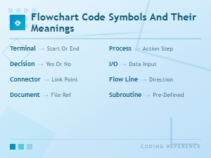 Flowchart Code Symbols and Their Meanings: a Complete Visual Guide